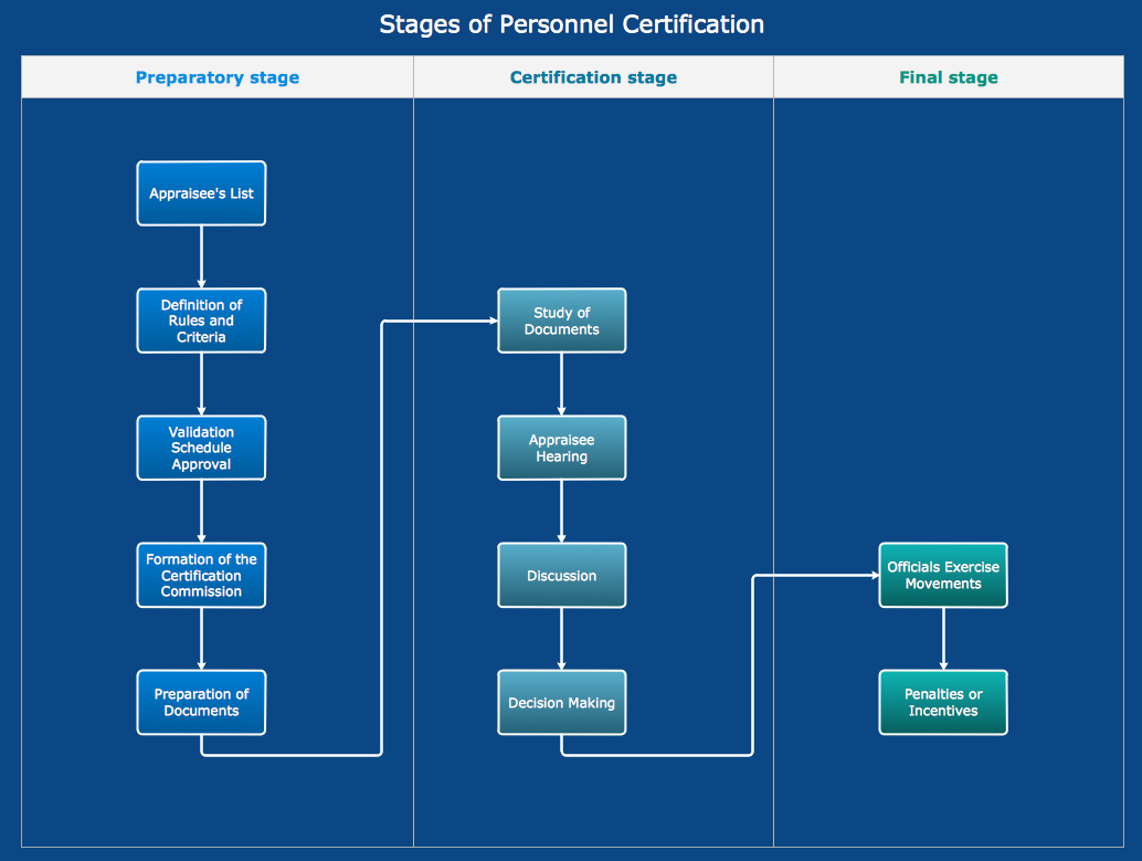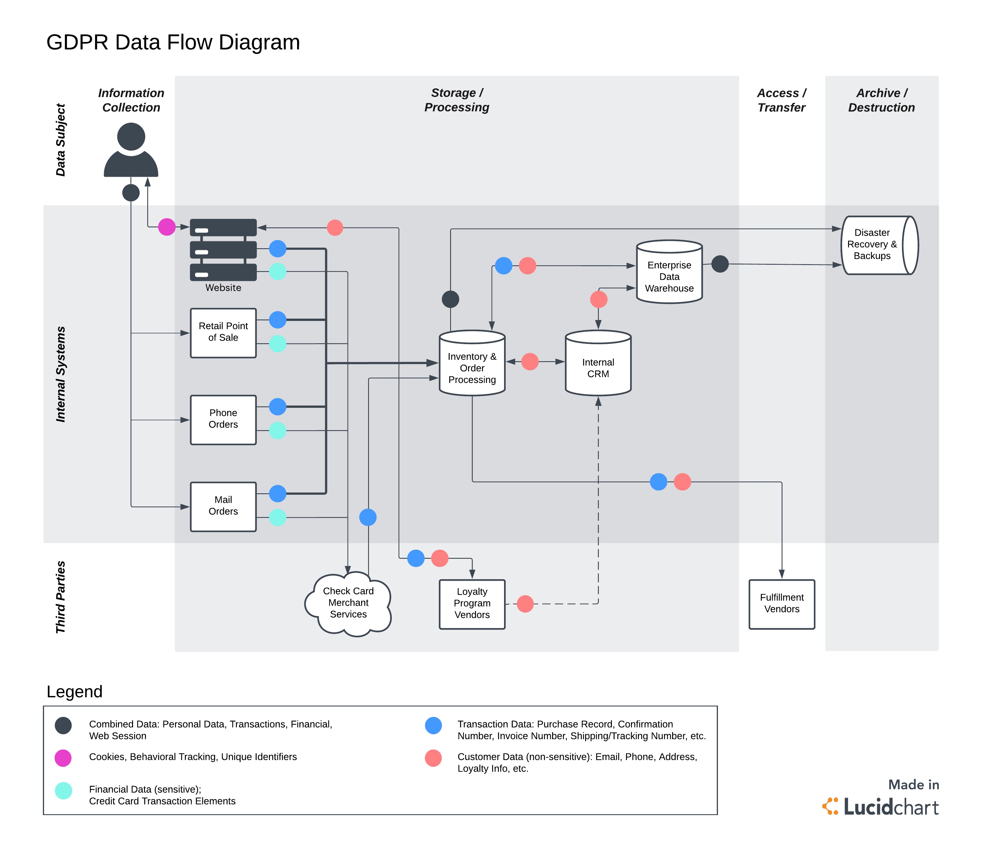

Sample process flow diagram iso#
On a sophisticated PFD, you may need to use standard symbols such as ISO 10628 to clearly communicate and collaborate with diverse audiences such as other companies or agencies. If you’re using diagram software, it will include a set of symbols to use. Remember who your intended audience is, and do whatever makes the most sense to give them what they need for the intended purpose.
Sample process flow diagram software#
The software also may help you to highlight missing data in your diagram.īe consistent with your symbols to avoid confusion. With intuitive software like Lucidchart, it’s not hard to create professional-looking diagrams to clearly communicate a process flow to your colleagues. Move on to diagram software once you have your information. Just capture the information on sticky notes or sheets of paper. Don’t worry about the chart itself at first. If you’re new to PFDs, try it out, gathering sufficient detail for your purpose. These diagrams can have a lot of value for even a basic process. Now the diagram(s) can be used for its intended purpose of documentation, quality assurance, improvement or whatever other goal there might be.Make any necessary changes, additions or deletions in collaboration with them. If you’re modeling a brand-new process, study whatever data is available, including standards for whatever is being produced in the process.ĭraw a draft diagram and confirm it with people involved in the process. Study the equipment, activities and relationships through observation and interviews. For a smaller, more basic process, you might do this yourself, perhaps even starting with sticky notes. For a sophisticated process, different versions of the diagram may be drawn to communicate with people in different roles.įor an advanced process such as at an industrial plant, the research may be done through a project team, quality control group or a consultant. P&IDs take the conceptual aspects of a PFD and add detail about the equipment, process sequence, process and utility piping, bypass lines, instruments, valves, vents, drains and other items.ĭefine the scope of your process to be studied and what you hope to gain.ĭecide on what level of detail is needed for your purposes. On the other hand, a Piping and Instrument Diagram (P&ID) is more technical, describing mechanical details for piping designers, electrical engineers, instrument engineers and other technical experts who need this detail more than they need process details.

The process flow is usually shown from left to right, and arrows show flow direction.

A rectangle is usually used to show a piece of equipment and labels illustrate function. Each block can depict a single piece of equipment or a stage in a process. These are also called Block Flow Diagrams and Schematic Flow Diagrams. When the diagram needs to show multiple unit processes at a plant, it becomes more of an overview, containing less detail. Typically, these more detailed items are omitted: Values often will include minimum, normal and maximum.


 0 kommentar(er)
